


Here’s what you need to know to build structural timber floors, starting with understanding the potential strength of this renewable material.
In this article we cover:
- Step by step DIY guide to building a structural timber floor
- What you’ll need to build the floor
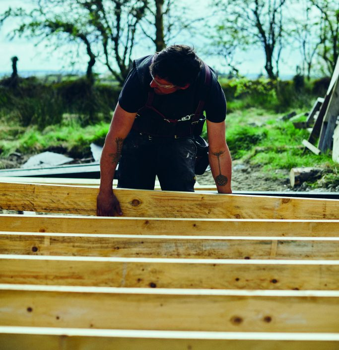
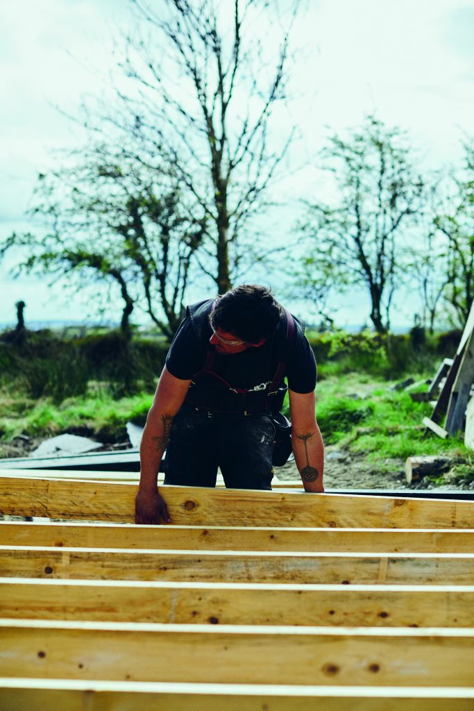
- Diagrams and photographs of the process
- Key terms explained
- Understanding spans and timber strength
Building our homes up off the ground is standard practice in the majority of the world’s wet or humid countries. It protects us from rising damp and rainwater runoff as well as making services and utilities easy to access and repair.
There are several ways to build a structural timber floor. This is one such method, but all concepts are the same – it is all about gravity and load disbursement.
Considering the loads which will impact your structure is necessary before you begin constructing. Refer to the span chart before you begin planning your floor.
To make a 4mx4m suspended timber floor, you will need 14 lengths of pressure treated timber 150mmx50mmx4m, 100 framing nails size 90mm, exterior wood glue, 3 clamps size 200mm.
STEP 1: If you’ve already poured your concrete foundations and did not allow for any way to attach a timber frame, it is not too late.
You can make the transition from masonry to timber by drilling a hole through both the timber and the concrete and installing an anchor bolt. As you tighten the nut, the sleeve around the bolt will expand and grip within the hole.
STEP 2: You are now going to create three laminated beams. Lamination is the process of joining timber together to create a thicker piece of timber.
Cut six lengths of timber, each 4m long. Lay two of your pieces of timber beside each other and apply your exterior wood glue to the flat 150mm wide surface of one of the pieces. Be generous with the glue but don’t add too much that it spills out when you press the two pieces of wood together. Place the other piece of timber flat onto the glued piece, pressing them together firmly.
Line up the two pieces of wood accurately, and fix one nail in each end so that they are securely attached. Stand this piece of combined wood on its long edge and apply the clamps evenly along the length of your wood to press it together.
Add nails, in a zigzag pattern, at 30cm intervals, the whole way along. You can drive the nails in at a slight angle to ensure a very tight grip. You can now remove the clamps and let the nails hold your laminated beam together until the glue dries. Repeat the process with the other four pieces of wood to create three breams which are 150mm by 100mm by 4m long.

STEP 3: You have options when it comes to transitioning from your masonry work in the foundations
to your carpentry work. You can make or buy steel brackets which you can anchor into your foundations using concrete anchor bolts.
These saddles support your timber and raise it away from any potential damp. Or you can anchor a pressure treated timber plate directly on the foundation concrete and use ordinary timber screws to attach your beam.
Place your laminated beams across your foundations and attach them by whichever method you have chosen.
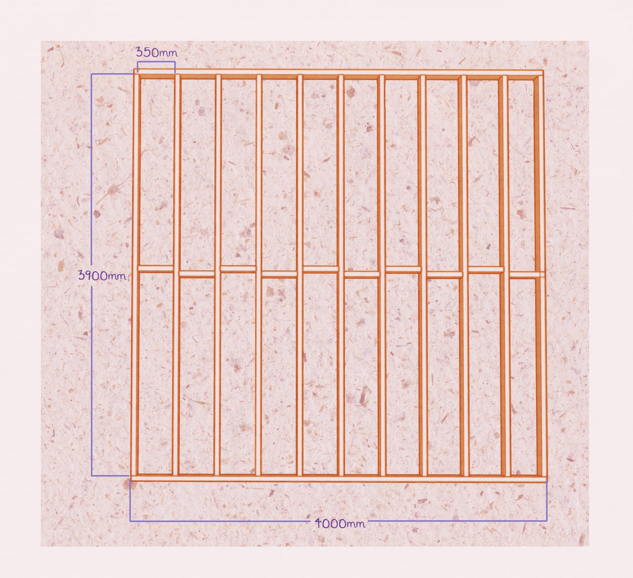
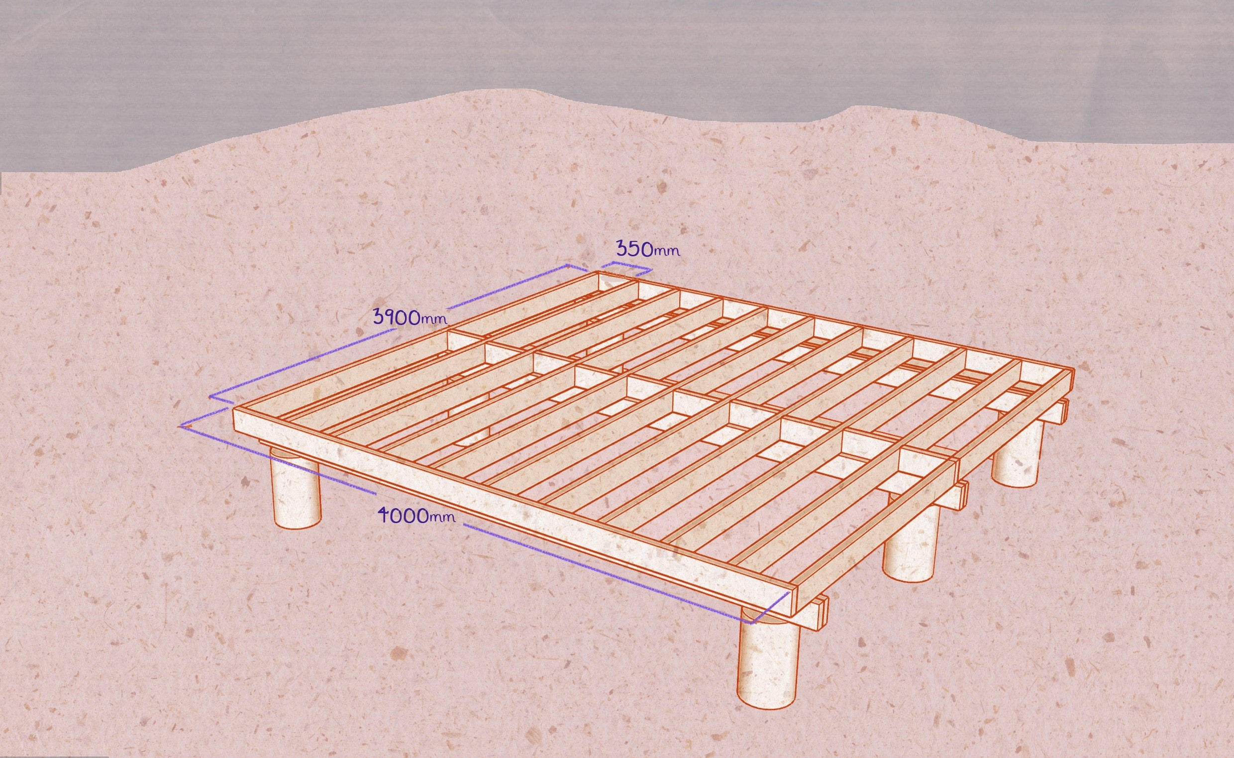
STEP 4: Now cut two more lengths of timber 4000mm (4m) long and cut 11 lengths at 3900mm. The
shorter lengths will fit between the longer lengths and you will end up with a 4mx4m square.
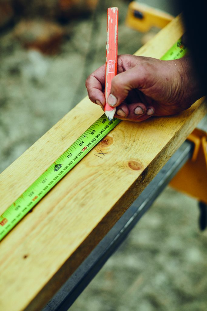
STEP 5: Mark two 4m lengths at 400mm centres and mark an X on the side of the line where your timber is to be fixed. Mark both pieces identically.
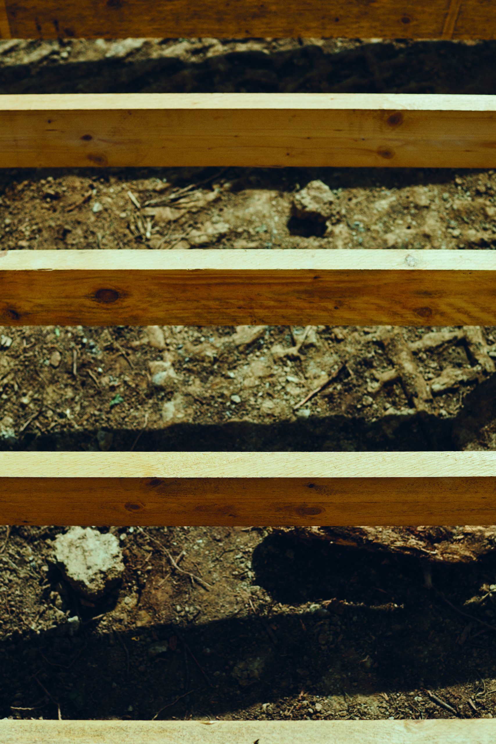
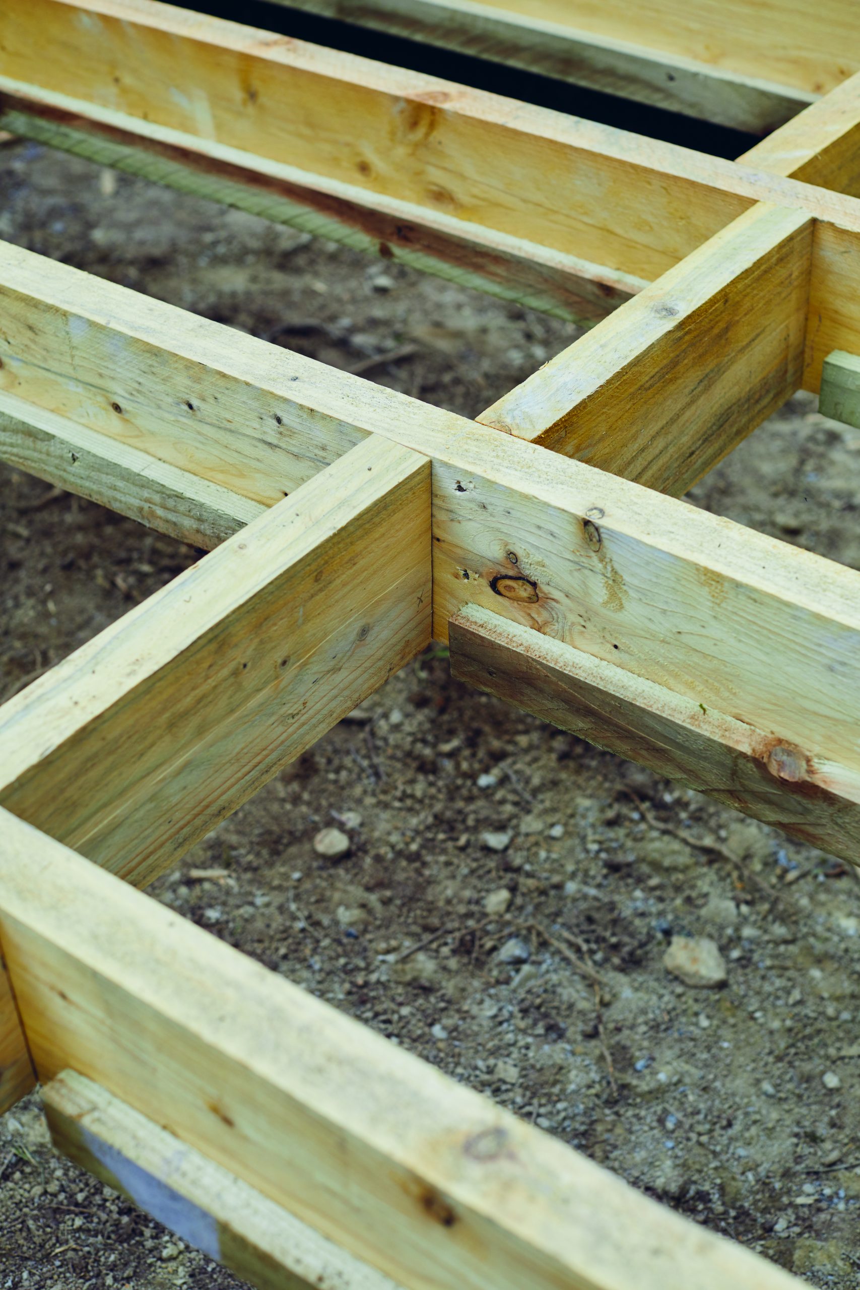
STEP 6: You can now lay all your timber across your laminated beams. Do this so that the 3900mm lengths run across all three laminated beams and the 4000mm lengths fix to the ends and hold them all in place.
STEP 7: You can now nail your structure together, making sure to line up your marks and crosses with your timber. Always making sure you are on the correct side of the line.

All photography by Shantanu Starick
Key terms
Stress can be understood as the amount of force being applied to a material over a certain area, whether that force is gravity, a car or an elephant.
Strain can be understood as how much a material stretches or compresses under a given stress.
Strength of a material can be determined by how much force is required to break it. Materials
should not be compared with each other by their strength alone, but rather by what makes them strong. The strength of a material is the potential stresses it can carry, combined with the strain it might experience under these stresses.
Elasticity or rigidity of a material can be understood when we divide the stress by the strain. All materials fall somewhere on a scale from rigid to elastic. And all structures are made of a considered combination of both types of materials.
Span is the gap between two supporting elements. Understanding span is critical to managing load displacement in our buildings. It allows us to determine the grade, dimension and quantity of timber necessary to safely achieve our supporting structure.
Centre positioning also known as edge to edge positioning means that the distance between the
studs is calculated from the centre of one stud, to the centre of the next stud, as opposed to the gap between them.
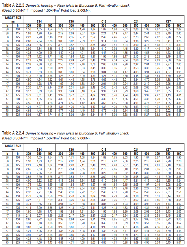
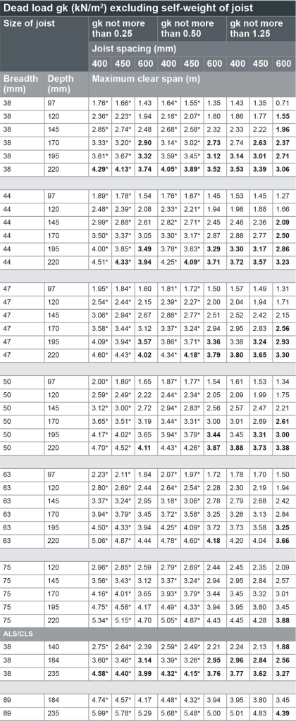
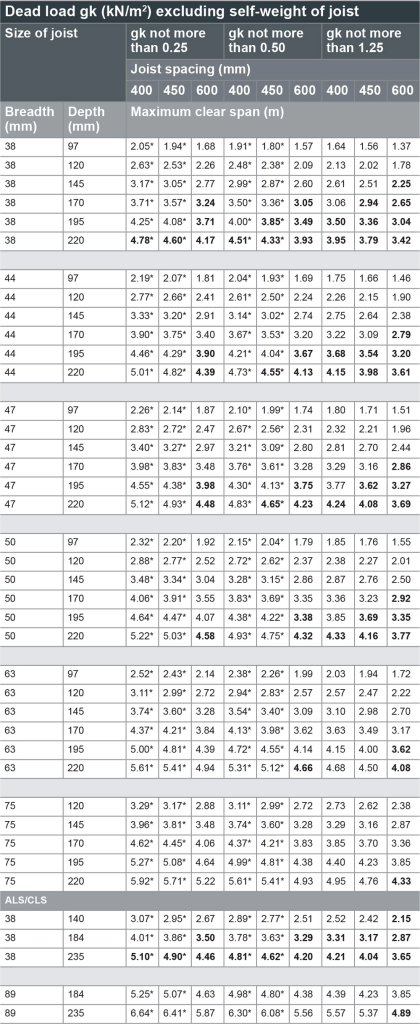
A span chart will help work out how many roof rafters or ceiling or floor joists we will need to cover a certain area, as well as the specific thickness and height these planks must be.
There are numerous free span charts available online* and understanding the language of these charts makes them a useful reference. It is important to ensure you are referring to a span chart that is relevant to your location, material and end use.
These charts can be used in both directions, meaning if you already have the timber you plan to use, the table will show you how far apart your joists will need to be. Similarly if you have already decided the span, the table can show you which dimension of timber will be most suitable. The terms in a span
chart are as follows:
Loading refers to the quantity and type of load that the joists are designed to carry. A load can be defined as the weight or source of pressure which is experienced by our structures.
The average three-bedroom home weighs somewhere between 36 and 80 tonnes, which is the equivalent of six to 12 adult elephants or 500 to 1,000 people. The perpetual pull of gravity, which pushes the weight of our house down into the ground, requires an equal and opposite resistance to prevent it sinking down into the earth’s surface. The role of foundations is to not only connect us to solid ground but to evenly disperse the weight of the building over as great an area as necessary.
Some load is referred to as dead or static. Some is referred to as live or active. Dead load does not move. An example of this would be your appliances, furniture and the building materials themselves.
Live loads refer to the weight of occupancy and suggest vibrations and movement. An example of this is the second floor of a building where human activity would affect the load at any given time. Foundations are designed to work specifically with your building and to spread a point load, which is a load focused on any one point of the structure, right across the foundation.

Strength class of timber refers to the suggested grade of timber permitted for use. Before a tree is milled, a certifier will examine the end grain of the timber and assess the species and grade. They then divide it into different strength classes. The higher the grading, the stronger the timber and the greater the distance it can span.
Spacing of joists refers to the distance between your joist members. This is measured between the centres of each joist, rather than the space between them. The more often your joists occur within a space, the greater the number of joists and thus the more elements there are to disperse the loads.
Target size refers to the dimensions of the joists. Joists are always placed in a vertical orientation, so they should always be taller than they are wide.
Maximum clear span is the maximum distance the joist can carry the load.
*Editor’s note about span charts: The NHBC publishes a span chart for NI as reproduced below, and Woodspec has guidance for ROI as reproduced in the text above. Always refer to current building regulations and consult with a qualified structural engineer
Bold text = normal bearing of 40mm to be doubled
Bold text = normal bearing of 40mm to be doubled