In this article we cover:
- How to install window heads, sills and reveals in an ICF build
- Cavity closers: what they are how they’re used with ICF
- Sealing up around chimneys
- Internal walls made of ICF
- Main watchpoints for this stage with images
There is no need for traditional horizontal and vertical damp proof courses (DPC) at window and door openings in ICF construction.
As you’re constructing a reinforced concrete building, the need for precast window/door lintels for smaller openings and steel/special lintels for larger door and window openings is now eradicated.
Your structural engineer can specify additional rebar over the window or door heads that will allow the concrete core to carry the window and door openings, and for larger spans it can also eliminate the requirement for intermediate supports such as steel/concrete columns.
If you need a reinforced column, to provide additional support, you can have it placed vertically and incorporated into the core of the ICF walls.
Cavity closers
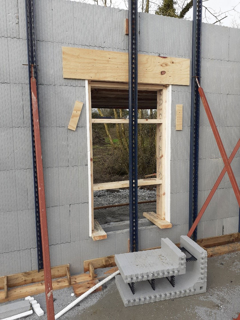
Most ICF system installers have preformed cavity closers. These are either flat and rebated, or have raised reveals. These allow the window or door frame to sit tight against the head and reveal. From a thermal perspective and airtightness perspective, this is an excellent detail.
However, there is one consideration. That is you need to allow for an extra deep frame or be willing to live with over 25 per cent of the window frame being hidden behind the reveal.

See Figure 1 for the pre formed closers both over the head of the window and on the reveal of the window, ready for the concrete pour. Figure 2 shows a rebated vertical closer waiting to receive a door frame

Cavity closers are propped from the outside with a timber shutter before the pour. If you have windows of the same dimensions at first floor level and so on, these timber props can be reused in the second pour. That’s if they’re removed carefully.
Window sills
Another issue to be aware of is the placement height of window sills. I have found on numerous projects, whilst carrying out my pre-pour inspection, that the sills were being placed at the incorrect height off the finished floor level.
You need to allow for the height of the sills in the window opening when installing the ICF formwork. See Figure 3 where the outside leaf of EPS has been cut down to allow for the sill and the inside leaf has been left up to help insulate the rear of the sill.
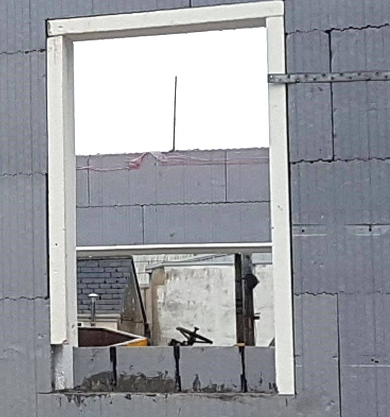
I have also encountered instances where no allowance had been made for the sill overhang, or ears of the sill as they are also known.
The sill is not to be rebated but the ICF is to be cut to allow for the sill. This is much like the installation of the sill in a traditional blockwork building, leaving you with the required sill overhang on either side of your window opening.
The installation of the DPC around the window sill is still extremely important and should be installed with care and not trimmed until the finished render has been applied.
Chimneys
Although most of the new dwellings today install a heat pump for space heating and hot water, with underfloor heating at the ground and first floor levels, we are finding the majority of our clients like to incorporate a solid fuel stove into their design.
But chimneys are not covered in the majority of ICF system suppliers’ Agrément Certificates or BBA Certificates. This does not mean that you cannot install a stove with a chimney system if it is detailed correctly, which in turn will guarantee that it is in compliance with Technical Guidance Document Part J (ROI) / Technical Booklet L (NI).
I would also recommend that you seek the advice of an approved HETAS (Heating Equipment Testing and Approvals Scheme) installer and also engage with them to install your stove or similar heating appliance.
Internal walls
Internal walls both load bearing and non load bearing can be made of ICF instead of traditional masonry block or stud (timber or metal) internal walls. The most important connection is between the loadbearing internal walls to the ICF external wall.
This should always be detailed by a structural engineer. If using block work for the loadbearing wall, I would highly recommend the use of thermal blocks where the block wall butts against the ICF wall’s concrete core.
If using ICF internal walls make sure that the wall forms used are specified for internal use. I have seen ICF internal walls with 150mm on one side, 150mm concrete core and 50mm on the other side of the concrete core. Not alone are you losing valuable space but it’s quite difficult to find the web in with a plasterboard screw on the 150mm EPS side of that internal wall.
Before pouring, make sure that the walls are all plumb and level, especially around internal door openings. This means there needs to be sufficient propping and bracing of all the internal walls.
The internal finish to the EPS wall is normally a 12.5mm plasterboard slab screw fixed to the PVC/Aluminium webs at 200mm centres in the ICF block.
Always remember to use green (water resistant) plasterboard to wet areas. As I mentioned all first fix electrical can be carried out with speed as the trades can easily chase the EPS before the plasterboard slabs are put up. This then receives a skimmed finish with a selected paint or other finish.


