[adrotate banner=”53″]
In this article we cover:
- Why ventilate
- Differences between ventilation systems
- Ducting and system types
- How to compare costs
- Focus on heat recovery ventilation: branch v manifold systems
- Design, specification, noise, installation and commissioning of systems
- Filters and maintenance
- Troubleshooting the most common problems including water leakage, condensation and excessive noise
In not-so-well insulated homes, purpose-built vents in the windows and walls provide unregulated ventilation. The lack of control over how much air is allowed into and out of the house makes these vents unsuitable for low energy homes. In a new build or in an existing home that’s undergone an energy upgrade, it’s therefore more than likely you’ll need to rely on a mechanical system.
With the number of ventilation systems on the market specifically designed for domestic use, it can be a minefield. So here’s an overview of what systems are available, what is suitable for where and what to bear in mind when specifying your unit.
Why ventilate at all?
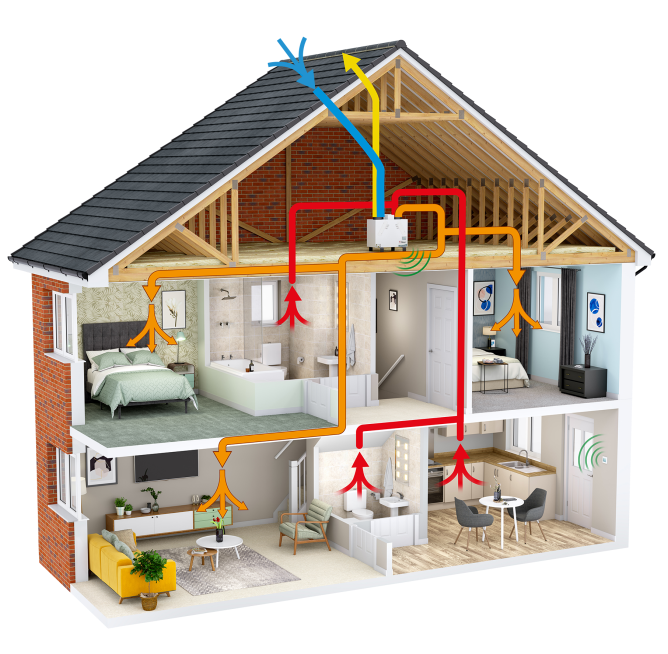
Very simply, to breathe fresh air. A whole house ventilation system will extract stale air from the home and replenish it with fresh. The aim is to reduce indoor pollutants, odours, carbon dioxide and prevent excessive levels of humidity. High moisture in the home can lead to health problems but also to condensation and mould forming.
With some areas of the home, for example the roof space, ventilation also has an important part to play, especially if you’ve added insulation. In order for the insulation to work the way it’s meant to, it shouldn’t get wet or humid. In a cold roof, whereby the entire roof space is ventilated, usually this means natural ventilation at the eaves. A vapour barrier on the warm side of the insulation is also needed to prevent moisture getting through to it from the house.
If the roof space has been converted and the insulation placed between the rafters, usually with plasterboard and a vapour barrier on the inside, provision will be made for air to flow over the felt above the insulation and underneath the slates from the eaves to the ridge to prevent condensation.
This ventilation may not be necessary where the insulation meets/joins underneath the rafters and complies with all the other criteria of a ‘warm roof’. In this case the air space within the roof void will be the same temperature as the rest of the house and will need to be changed from time to time along with the rest of the stale air in the dwelling, by the ventilation system.

Types of ventilation systems
First off, know that there is no ‘best system’: each ventilation system serves a purpose and it’s very much a case of ‘horses for courses’. As with all building projects, your ventilation strategy needs to be ‘fit for purpose’, which means that it must comply with the Building Regulation requirements for your build and, just as importantly, it must meet your needs.

Houses traditionally relied on a combination of natural ventilation (‘trickle vents’, also known as ‘background ventilators’, in the living rooms/bedrooms) and standard mechanical extract ventilation (extractor fans in the bathrooms).
The trickle vents in the windows are incorporated in the frame in the form of sliding louvers; in the wall they consist of a hole with a grille on each end – usually plastic on the inside which can be opened and closed, and galvanised steel on the outside.
This system is commonly found in older houses or those with air leakage superior to 5m³/h/sqm whereby air leakage or permeability is measured at 50 Pa. Pascal is the unit used to quantify pressure.
In many cases issues arose because the mechanical extract fans were fitted with long runs of ducting. This practice can lead to a significant drop in performance which in turn causes persistent humidity problems in wet rooms as the fans are meant to be fitted at the extraction point. You can now get fans that are designed to be used with long duct runs but they are considerably more expensive.

The use of flexible ducting was also prevalent in the past; these are no longer commonly used as installation must be precise to avoid condensation within the pipe and eventual leaks.
That said, if fitted correctly natural ventilation and standard extractor fans can, from a ventilation point of view, provide adequate air changes.
The main drawback of this combination from an energy point of view is that the amount of fresh air allowed into and warm air flowing out of the home is often excessive as it is unregulated.
This has led to the common practice of blocking up the vents to avoid draughts but doing so has disastrous consequences for indoor air quality, i.e. more pollutants and more humidity build up in the home.
This is why positive input ventilation, which allows you to control the amount of fresh air that is brought in, is an attractive option if upgrading an existing ventilation system – or had none at all.

Another popular option for retrofits is demand controlled ventilation as it not only regulates the amount of incoming air based on demand (sensors detecting humidity/pollutants in the rooms regulate how much air is allowed in), but also extracts stale air from each room in the house.
The ducting required to be installed is only on the extraction side, which makes it less cumbersome to retrofit than a ducted system on both ends. In fact demand controlled ventilation is becoming an increasingly popular alternative on new builds as well.
Heat recovery ventilation
The most popular choice for the new build market, but also the most costly, is Mechanical Ventilation with Heat Recovery (MVHR).
Most one-off houses are extremely energy efficient with high levels of insulation and airtightness below 5m³/h/m².
It is in these conditions that heat recovery ventilation can, if designed and installed correctly, be the most efficient option. Even in less well insulated and airtight homes, when calculating your energy rating you will find that heat recovery ventilation contributes to a higher grade (the other systems don’t rank as high).
There are two options within MVHR systems, tee’d (commonly known as ‘branch’) or manifold. Your M&E consultant will be able to advise you on which system to choose in your particular circumstances.


Branch systems rely on diminishing duct sizes to work; the duct size starts from the MVHR unit at, for example, 200mm and reduces to 180mm, then to 150mm and finally to 125mm or 100mm diameter for the connection to the termination diffuser. The ‘trunk’ runs from beginning to end; off of this main line ‘branches’ are brought into each of the rooms. The ducting is often made of uPVC but it’s preferable to choose galvanised steel. Proprietary branch systems must meet the DW144 Class 2 standard.
Manifold systems use large diameter twin walled ducting to link up to the fan and then to the manifold (also known as plenum boxes). The manifold ‘box’ has a number of adjustable outlets which connect to smaller diameter ducts and these are brought individually to each room. Manifold systems are tested to EN 13141-7.
The key elements to an effective MVHR system are as follows:
Design
Starting with a detailed design will enable a detailed specification; the two are often done by the designer (often referred to as a ‘specifier’, a role that is usually taken on by an engineer or, if suitably qualified, an architect). The design should clearly show the location of the unit, primary supply, primary exhaust and the air distribution system. It should give the exhaust and supply airflow rates in the relevant rooms and these should be shown with the unit operating at both low and high speed.
If correctly designed, the MVHR unit will deliver the maximum required airflow whilst operating at no more than 75% of its capacity – this is essential to maintain both motor and thermal efficiency across the heat exchanger. The duct runs with their dimensions and the location of each air termination diffuser should also be shown to scale on the drawings, likewise how the condensate connection to the waste water pipe will be made. Although it may be stating the obvious, the design should match the specification.

Specification
This is the second step to success. A detailed specification should be prepared, not just for compliance with the relevant Building Regulations but to ensure that the system will be fit-for-purpose and provide adequate ventilation for the occupants and the dwelling. The specification should cover the unit and the air distribution system (type of ducting); what airflows above the minimum standard are required (if applicable); the ventilation capacity of the unit and the ducting type and its dimensions as well as maximum noise levels. The noise level is also specified at the termination diffuser.
If sections of the air distribution or the unit are in an un-insulated section of the dwelling and require insulation, this should be specified and not just relied on as being a regulation or the responsibility of another trade! The required efficiency across the exchanger and the noise levels should also be specified. It is equally important that the specification is achievable from an installation perspective, particularly in regard to the air distribution.
Noise
Where the unit is located, the type of air distribution system and the operating performance of the fan motors all have a bearing on the question of noise. For instance, if a dwelling requires 300m³/h @ 170Pa when on boost, manufacturers usually recommend supplying a unit that is capable of 400m³/h @ 170Pa. Ideally, a unit should not operate at more than 75% of its capacity when on boost. This would equate to 50% of its capacity in normal operating mode. Also, the velocity in the tributary ducts should not exceed 1.5m/s (small diameter or cross section equivalent ducts cause the air speed to increase).
Another potential contributor is the installation of the MVHR unit itself – noise can travel through the structure of the dwelling as a result of the unit vibrating. To prevent this, the unit needs to be decoupled from the structure with anti-vibration mounts. Alternatively, independent mechanical housing can be used.

Duct-borne noise as described above (from the fan, vibrations, etc.) is uncommon when the system has been properly designed and installed. In a branch system, best practice is to use larger diameter (125mm) branch lines and up to 250mm diameter main lines so as to carry the necessary high volumes of air at low velocity (depending on the size of the system). This way the sound is properly attenuated in the branched lines that connect to the main, or trunk, line.
However noise from conversation and other household activities such as turning on a tap can travel from room to room through the ducting. To avoid this, cross talk attenuators are often used but bear in mind that for those with very good hearing it may not always be a foolproof solution! In manifold systems there is less risk of this type of sound transference as each room is individually ducted to the manifold, but if fitted incorrectly any type of ducting can cause noise.
In general, there is no point specifying a system with less than 25dB(A) unless your budget will stretch to this. That said, specifying that noise levels from diffusers must not exceed 28dB(A) on the low setting and 30dB(A) on the high setting is very realistically achievable, even without attenuators.
Understanding fan pressure
Every ventilation system has to deal with pressure, which is created by the components of the air distribution system (roof and wall cowls, primary ducting, manifolds, attenuators, termination diffusers, cross section equivalent of the tributary ducts, volume and velocity of airflow and the external pressure of the unit itself). For example, if a system has been designed with 125mm and an installer recommends using a 75mm duct then this will compromise the system.
The reason pressure is important is that the more there is, the harder the fan has to work. Most MVHR units are designed to operate with no more that 150Pa in the system. If the pressure exceeds 150Pa, many systems can lose half of their capacity so ideally, a system should be designed with a maximum resistance of 180Pa.
Bear in mind that any system must be correctly maintained to avoid dirty ducts etc. which may compromise its effectiveness.
Every manufacturer has a ‘fan curve’ which allows the designer to chart the volume of air capacity against the amount of pressure the unit can handle. Many manufacturers now produce MVHR units with constant volume fans that can handle increased system pressure and still deliver the required air flow.

Heat exchangers and efficiency
Modern heat exchangers are extremely efficient, that is, most of the heat gained from the extracted stale warm air can be transferred to the fresh cold incoming air. However beware of claims of very high heat exchanger efficiencies – evidence of same should always be sought.
In a residential setting you may come across the rotary thermal wheel but the counter flow exchanger is more common. Both types of exchangers are equally effective, the primary difference is how they deal with the moisture in the air. The counter flow exchanger is fitted with a condensate drain which allows for all the excess moisture to be removed from the dwelling. The thermal wheel exchanger replaces a certain amount of the moisture being removed from the dwelling back into the supply air.
Irrespective of which exchanger is used, the designer needs to know the efficiency of the exchanger they intend to specify. Default values (e.g. in SAP-Appendix Q) will not provide a good indication of what’s going on in your house and therefore can’t be relied upon for the specification as there are other variables to consider such as size and type of ducting.
Most manufacturers will provide a technical graph which shows how the efficiency of the exchanger is affected with changes in temperature (external and internal), volumes of air and the velocity.
Filters
Nearly all manufacturers offer the full range of filters from G3 up to F9. F7 and upwards are classed as pollen filters, produced from a filter media which can be either paper or cloth, is pleated and provides a high micron filtration level. The standard G3 filter is cloth with a lower micron filtration level. The filter on the input is there to remove pollutants, etc., and on the output to help keep the exchanger clean.

Installation
Installation of MVHR systems is simple, or at least it should be! If the design and specification are detailed and easy to follow, it greatly reduces the potential for problems. In NI, all approved suppliers and installers must have BPEC recognised accreditation. Installers holding this qualification are therefore fully trained, qualified and certified to design and install ducting systems, just as a qualified electrician can wire your house based on your requirements. A basic floor plan with diffuser locations marked on them (which has previously been agreed by the customer) is all a professionally trained installer needs. In RoI, there is no real training for installers so a detailed specification and drawing schematic for each application is usually necessary.
Installation problems due to poor workmanship, are a separate issue.
The key points to consider with installations are:
- All of the joints in the ductwork, throughout the system, must be airtight and sealed correctly.
- Flexible ducting is not recommended by building regulations and as such rigid ducting should be used wherever possible. Sharp bends should also be avoided. As compared to flexible types rigid ducting improves the performance of ventilation systems for technical reasons, i.e. improves airflow, minimises pressure loss and heat loss (which leads to condensation) and ensures correct bends are kept in place, but also for durability and the fact that they will be less noisy.
- The use of bends should be kept to a minimum (this is the responsibility of the designer).
- ‘Open’ ducts on site should be sealed until connected to the unit, manifold and/or termination diffuser.
- Ducts should be checked for building debris and dirt before connecting and sealing the system.
Just as you would conduct an airtightness test on a house, I would always recommend an operational airflow check of the MVHR system before you plasterboard and/or box in the ducts, as this will verify that the air distribution system is fit for purpose and without leaks.
Commissioning
Commissioning happens when the installation is complete. The process involves checking that the volume of air supplied to the rooms and the rate of extraction from the wet rooms are correct and abide with the pre-specified settings. It also ensures that the switches and general operation of the system is functioning as designed and manufactured.
Once these checks have been conducted, the installation will have to prove compliance with Technical Guidance Document F (ROI) / Technical Booklet K (NI). The installer has to supply a Balanced Commissioning Report to Building Control in order to have the house passed. In NI, this is only acceptable if prepared by a BPEC approved engineer and it is usually a representative of the company supplying the system. It is recommended that the end user is present.
At this point the handover commissioning certificate is filled in to match readings from each diffuser, and ensure that insulation, sound attenuators and the airtightness of any exposed duct is correct. The end-user receives the handover of all operation and maintenance manuals and is shown how to use it.
The checks are carried out by a competent person using a calibrated (INAB or equivalent), anemometer, a device measuring airflow and velocity. It is important to ensure that the anemometer is suitable for low-volume and low-velocity measuring, and has a current calibration certificate. If there are discrepancies between the actual and specified airflows, they can be adjusted through the termination diffusers (on a branch system) or at the manifold.
Maintenance
All systems require maintenance and the cost of consumables and manufacturer approved servicing should always be considered when purchasing a MVHR system. Maintenance costs vary and some machines require higher levels of after care, also, filter prices differ considerably from manufacturer to manufacturer.
Servicing at regular intervals, every year or two, is considered good practice but is not essential. The Passivhaus Institut recommends the cleaning of ducts every five to 10 years.
If the system is not performing your first port of call should be the supplier. MVHR warranties are generally on a ‘return to base’ basis, which may be impractical if the company is not located in Europe. It is important that you receive a written warranty from the manufacturer or their distributor in ROI or NI.
That said, filter cleaning and filter changing are the only items that really need attention and these are usually done by the occupier of the house as the procedure is straightforward. Ideally you should wash them (or if possible replace them), every six months. It is best practice that when doing this the inside of the MVHR unit is vacuumed to remove any dust build up around the heat exchanger.
Most common problems
I have seen many problems with MVHR systems and in most of these cases it is not a single-fault issue. Nearly always what happens is that at least one of the elements outlined above has been compromised or left out completely. Other common problems include:
Last minute changes If the homeowner decides to change the location of the unit or the use of a room, installers should immediately contact the system designer (they definitely shouldn’t make changes on the spot!) because a re-design may be required for the system to function properly.
Water leaking This can be caused by the condensate drain attached to the MVHR unit being incorrectly fitted or not fitted at all. Water leaking through termination diffusers and collecting in ducts is likely to be due to uninsulated ductwork: when warm moisture-laden air is extracted through a duct that rises into a service void (attic) or cold space, it condenses due to the temperature differential. Water droplets then form and fall back down through the diffuser.
Noise Undersized units, undersized ducting, excessively long duct runs and too many bends can all cause noise, as can using “roof tile vents” as the primary supply without sufficient free area.
Unbalanced systems An incorrectly-balanced system can lead to draughts in some rooms and cause excess moisture in others.
Excessive condensation in some wet rooms This is usually a design issue, particularly with north-facing walls which are tiled floor to ceiling and have high-volume power showers. Wet rooms with these conditions require higher levels of ventilation.
Cost considerations
The most expensive system is not always the best, indeed, in some cases the cheapest will deliver exactly what you need! However, if two bona fide companies are quoting against a specification (genuine like for like), there should be very little difference between quotes, so the cheapest won’t necessarily be a lot cheaper than the competition.
This is also true of the duct manufacturers; if you compare ‘like for like’ you will find very little difference between prices. If a PC sum has been based on a specified product then all equal and/or approved products will be very close to the PC sum. It will not be possible to find the ‘same’ product at half the price. Any contractor offering a system for half the PC sum will not be able to give you technical product data matching the specification.
Ciaron King & Astrid Madsen. Additional information: BEAM Vacuum & Ventilation, NI tel. 79632424, www.beamcentralsystems.com; Satvic Environmental Building Services Design, NI tel. 90 659629, email [email protected]; XD Consulting, ROI tel. 0860476124, www.xdconsulting.eu


