In this article we cover:
- What is first fix?
- Checklist for running cables and pipes
- Getting set up for broadband
- Heating and ventilation watchpoints
- Checks for additional supports
- Stud wall watchpoints
- What to know about working with timber and structural components7
- Fireproofing, flues and combustion appliances: watchpoints
- Insulation and airtightness watchpoints
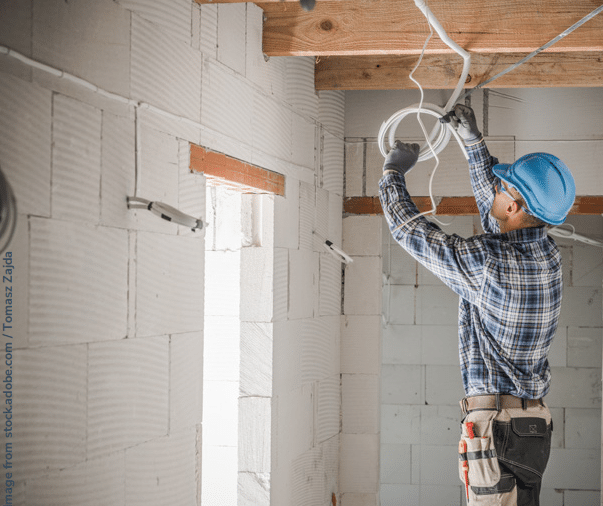
It is fairly common practice to bring the electrician on site to mark out the walls where chases need to be cut into the brickwork or blockwork to allow cables, conduits, sockets and switches to be buried within the wall structure.
A registered electrician will be familiar with installation safety around hazards such as wet zones and with the access regulations affecting placement of switches and sockets, so none of this should present a problem.
However, not everyone has a clear working knowledge of the regulations and guidance on the correct positions and dimensions of chases to maintain the strength of the walls. In fact I have seen some very worrying demonstrations of how not to cut chases, so it’s best to familiarise yourself with the regulations before work commences.

For a start, there should be no curved or diagonal cuts and there are strict limits to depths and widths. Chases in block or brick walls are ideally cut using a twin-bladed power saw which ensures that the correct depth and width of cut is maintained. Clearing out the chases is easily done using hand tools.
Avoid the use of impact power tools on brick or block walls. Hollow bricks or blocks should not be chased unless with explicit permission from the manufacturer.
Many devices and appliances operate wirelessly, which makes smart wiring installations a lot easier. You may however, prefer that the TV, PC or other smart devices be physically connected to the broadband hub using an Ethernet cable for a stable and fast connection.
If so, tell your electrician in good time. If not already done, decide on automated systems such as electronic windows, doors, gates, blinds, climate control, lighting, entertainment and security, etc. Again, keep the electrician informed.
Notching and drilling of timber joists for routing cables and pipes must be done with care and there is clear guidance in the building regulations for acceptable positions and dimensions.
If at all possible, run small diameter waste pipes parallel to joists. Obviously, larger diameter soil pipes and ducts cannot be taken through solid joists. There may be more than one trade involved, maybe at different times, so ensure that their combined requirements can be accommodated without causing structural damage.
Open-web joists are ideal for routing all sorts of services whilst avoiding any headaches regarding how it might affect the strength of the joists.
Checklist: Running cables and pipes
Identify where and what size holes in walls and floors will be needed. At this stage, you should have some idea of the fixtures and fittings you prefer, so check their vital dimensions such as inlets, outlets and fixing positions. Allow for insulation thicknesses around pipes and ducts and sufficient space to accommodate movement between services and fixed structural components.
Some holes will already have been formed and will be difficult to alter, such as those made for waste drainage upstands through solid floors. To take one example and regardless of what the internet tells you, there is no single standard distance for the dimension between a WC outlet connection and the wall behind, so always check in advance that your chosen products will fit with the work done on site, or vice-versa if possible.
All holes, notches or apertures in reinforced concrete (RC) elements should have already been built-in. Do not allow any site operative to cut or break out RC elements unless the structural engineer has approved it. In case of precast RC elements, always consult the manufacturer and obtain written instructions or drawings before any alterations are made.
WC soil pipes are typically 110mm in diameter and if routed vertically within the building, will usually run within a built-in void or a purpose-made plywood duct. Internal soil pipes should be acoustically insulated where they pass through a habitable room.
Some installations in the roof void will require a platform to allow future maintenance work to be carried out safely, such as space around ventilation units to fit replacement filters or around a water tank to replace float valve seals, etc.
Services passing through the external cavity walls should be protected and sealed (but not solidly embedded) in accordance with the working drawings. The only service item which will terminate within the cavity of an external wall is the electrical cable tail for the meter box.
Where permitted, copper water pipes in floor screeds should be sleeved or wrapped so that they can move freely along their length and at joints and bends.
All pipes, ducts and cables should be installed with allowance for expansion and contraction to avoid noise and damage.
All pipes, ducts and cables should be adequately supported with clips or brackets.
The colours of plastic pipes and ducts can be used as a preliminary guide to identification, but also check the markings and delivery paperwork against the drawings and specifications. Do the same for copper pipes.
Be on the lookout for cheaper and less robust duct pipe being used where drainage pipe has been specified.
It is good practice to run metal tape along the routes of hidden plastic pipes in walls and floors so that they can be more easily detected during future alterations or maintenance.
All services which will become hidden during the second fix must be tested before being covered, in accordance with the relevant regulations and codes of practice. Obtain written certification for each test procedure.
Heating and ventilation
The heating system needs careful consideration so that everything is in the most effective position. Heat providing equipment including boilers, heat pumps, solar hot water panels, and so on, plus all pipes, valves, drainage, storage and expansion vessels, underfloor heating pipes, thermostats and manifolds (or radiators), must have all been accounted for in the design.
Control equipment such as motorised valves and programmers, etc. will require input from both the plumber and the electrician.
Note that refrigerant pipes between the indoor and outdoor units of a split heat pump system must be insulated and properly protected.
If a mechanical ventilation and heat recovery (MVHR) system is to be installed, your designer will have ensured that sufficient space has been allocated for ducting and for the unit itself.
On the other hand, if the installation is a ‘post design’ decision, your joiners will need to know where to leave spaces for ducting within first floor stud walls and suspended floors.
Always get a layout design from the MVHR installers, which should ensure that all ducts and vents are correctly placed and that factors such as fire safety and noise control are not compromised by this work. Similar steps may need to be taken if a central vacuum system is to be installed.
Timber moisture content of 20 per cent or less is generally permissible for internal structural use, but timber joists will usually dry further after installation, so expect some shrinkage to occur. The shrinkage may not be uniform across a floor, so adjustments can be required to achieve level floor finishes.
Also ensure that ventilation ducts in suspended floors or over ceilings are laid to fall slightly towards their exit points on the external wall, or alternatively be fitted with condensate traps and
drains.
Also make sure that rigid ducting is used in preference to the flexible types. Not only will rigid
ducts provide better airflow, they will resist damage better and generally last much longer.
All vent ducts and their connections need to be meticulously sealed to prevent leakage.
Check if there’s a need for additional supports
Structural supports will be needed for heavier items such as baths, water storage tanks, battery packs, ventilation units and the like, even for heavy light fittings (i.e. chandeliers).
In timber floors and roofs, this will involve fixing additional supports which should be detailed on the working drawings. Some items may also require support from walls or beams.
Timber stud walls, for their part, will need to incorporate additional vertical studs or horizontal nogging pieces (aka noggins) to support fixtures such as radiators, shelving, wall-mounted wash basins or televisions, etc.

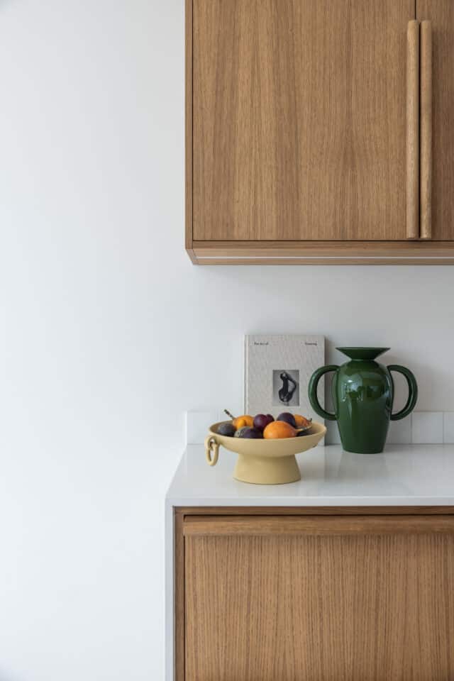
Fixing a layer of 12mm plywood on kitchen and utility room stud walls is often used to provide support for wall-hung cupboards and is especially useful where precise fixing points may be unknown beforehand. In areas which will remain visible, the plywood is covered with plasterboard.
Arguably, the plywood backing solution is essential in the case of lightweight steel stud walls, although kitchen fitters may have their own preferred methods such pieces between the metal studs or using cabinet fixing rails.
This may sound obvious, but shelving must be securely fixed and level. It can be useful to include some demountable shelves in cupboards. Limit the heights of shelves so that they do not encourage occupants to use lower shelves as steps up to higher ones.
Allow absolutely no alterations to structural steelwork or joint connections without first
consulting the structural engineer. Do not alter prefabricated roof trusses unless with prior written approval from the manufacturer. Alterations may require a structural design solution.
Timber walls
For all timber frame and stud walls, ensure that the timbers intended to support plasterboard are at the correct spacing for the plasterboard to be used. One face of a plasterboard sheet is suitable to receive plaster or decoration and the other faces inwards, so know which is which. Plasterboard sheets should have staggered joints on ceilings.
In general, all timber products both external and internal, should be produced using timber sourced from sustainable forests and certified accordingly by a body approved under FSC or PEFC regulations.
External timber frame walls are usually fitted with service voids on the internal side, so that services won’t pass through the insulation or the airtight envelope. Make sure that the voids are deep enough to take the largest diameter pipe or duct that will be required. Any cuts made in
vapour control layers (VCLs) or the airtight membrane will need to be properly repaired.

Fireproofing, flues and combustion appliances
At this stage of the build, fire barriers should already have been fitted where necessary in wall cavities, but other positions including around party walls and voids within floors, ceilings and roofs should be thoroughly checked for compliance with the fire safety drawings.
Fire stopping, using approved materials in accordance with the manufacturers’ instructions, should be provided around all services which penetrate fire resistant floors or walls.
A common oversight with combustion appliances is to build standard 200mm internal diameter
clay flue liners into a chimney before checking the specification.
Whilst a 200mm liner will serve the requirements for a standard open fireplace, your wood-burning stove might require a 150mm diameter flue to run at optimum efficiency and some might only require a 125mm flue.
Very often, the builder’s answer is to install a flexible stainless steel flue liner through the as-built flue and you might even be told that it is necessary for new-build stove installations. This is a
widespread myth. Unless you can envisage a time when you will revert to an open fireplace, there should be no need to install a larger flue liner than necessary.
Allowances must be made for minor irregularities in masonry units, timber and concrete. This relates to permitted tolerances in walls, ceilings, floors. It is important to know these, so check with your designer or certifier.
Double check the connection between the stovepipe and the flue liner in the chimney. This should be a purpose-made metal plate adaptor, connected and sealed to both pipes using an
approved fire-resistant product such as fire rope or sealant. If you end up with a flexible flue liner, a similar connection for support should be provided at the top of the chimney where the flexible liner meets the chimney pot.

Check any fill material such as vermiculite or a Micafill-cement mix, which might have been used to fill the space between a flexible flue liner and the original clay flue liners. Builders will often stuff mineral wool insulation around the top of the stovepipe to prevent loose material from falling out.
Checklist: Insulation and airtightness watchpoints
The keyword for fitting insulation anywhere is to fit it ‘snugly’. Don’t stuff it or squash it, don’t leave gaps and ensure that alternate layers run crosswise over each other.
Board insulation should have taped joints and layers must not be allowed to separate from each other to form air gaps.
When providing decking in a roof space, take care to support it 50mm above the level
of the ceiling insulation so that the insulation is allowed to breathe and does not
become compressed (compressed insulation is less thermally efficient). There is
a good choice of ‘loft leg’ components on the market to allow this to be achieved
accurately and robustly.
After every worker has been and gone from your roofspace after the insulation was
originally laid, get up there and fix it because nothing is more certain than it will
need it.
Before fitting ceiling insulation, ensure that approved caps are fixed over all light
fittings which have been recessed into the ceilings.
Ducts and pipes outside the insulated ‘envelope’ but within the building will all need to be insulated. A water tank in a ‘cold’ roof space should be insulated around the sides
and over the top but not underneath.
At an appropriate point during the first fix period, the potential air leakage of the dwelling will really benefit from painstaking attention to detail. Use good quality membranes, sealants and tapes and be thorough.
Run a final check on all insulation before it is covered up.


")


