
What if I was to say there is a detail in your house that is invisible yet can cause enormous damage and discomfort to your building and the people living in it? These places in your house are where heat escapes, rather than where cold air infiltrates. These losses can only be detected after construction with the help of an infrared camera; the points in which they are made are called cold or thermal bridges. Bad design and poor construction methods are the two main culprits, here’s how to tackle both.
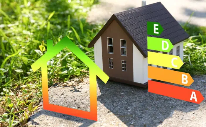
Cold (or thermal) bridges are details in a building envelope that cause unwanted heat loss through weak points of thermal resistance. It may sound like a mouthful, but it basically means that a part of your building envelope is letting heat escape at a substantially higher rate than other areas. As well as minimising heat loss, careful detailing and construction that avoids thermal bridges will improve the energy rating of your house; if you use the approved details you are also able to input the lower thermal bridge value into the DEAP (ROI software) or SAP (NI software) calculation, otherwise you will have to use the poorer default value. Indeed, you must get your thermal bridges calculated if you are looking to achieve as low a rate as possible. In the Passivhaus’ building software (PHPP) properly calculated thermal bridges can reduce the heat demand.
An easy example to see a thermal bridge at work is in a single glazed window where the heat in the house is transferred directly to the outside via the single pane of glass. On a cold day you will see the cold bridge as condensation appearing on the inner surface of the glass. Thermal bridging increases heat loss through the fabric of the building and in some cases results in surface, or interstitial condensation, which can in turn lead to mould growth.
We can immediately see the benefit of using double or triple glazing over single (although despite great advances in glazing technology, a wall will always perform better than a window!) but in terms of thermal bridging the frame is also crucial. For this the windows and doors must to be “thermally broken”, that is there needs to be an element of low thermal conductivity between the inner and outer frames to prevent the temperature outside to transfer through the frame. This problem is particularly prevalent in metal windows or curtain walling as these materials are better at transporting heat. In a residential setting old aluminium windows are among the most notorious at letting heat through; when buying new ones, a resin thermal break will be present both in the casement and in the frame in order to prevent cold bridging. In timber or uPVC windows this is not required as their thermal conductivity is much lower. With regards to the width of the spacer bars (space between the double or triple glazing frames) it will typically depend on the type of gas inserted between the glass. For example some joiners will use a 16mm spacer bar for air and argon but will opt for a 10mm spacer for krypton and 7mm for xenon. The wider the spacer bar and the “nobler” (more efficient) the gas, the better it will be at preventing heat getting through.

Apart from specifying the right kind of glazing, you will need to detail the design at critical junctions as well as make sure that the instructions are followed through during construction.
Design stage
Your design will need to identify where the thermal bridges could occur and put measures into place to avoid them. It typically happens at the junctions between plane building elements, e.g. at wall/roof and wall/floor junctions, and around
openings, e.g. at window jambs, where the continuity of the insulation is interrupted. The key areas to pay attention to are:
1. At window and door penetrations at the head and cill; you will need to consider the penetration junction in both plan and section drawings.
2. At the junction of the foundation to the external wall and all rising walls; as well as the foundation detail you will also need to consider the junction of any floor screed to the external wall.
3. At the eaves junction of the roof to the external wall; also at the gable where the inner leaf rises from the warm rooms to the cold attic.
4. Any balcony details where a balcony slab cantilevers from the house and is not separated thermally from the main building.
The proportion of the overall heat loss due to thermal bridging in average dwellings built recently is probably between 10% and 15% so small changes in construction detailing at these key junctions can deliver significant reductions in heat loss. The figure can be substantially higher with certain construction systems and in dwellings with particularly poor detailing. Note that so stringent are the thermal bridge details for the Passivhaus standard that as well as creating an uninterrupted and continuous insulation layer between all of the building envelope assemblies, it is recommended that windows are set into the insulating layer of the external wall and their frames be covered. The detail of the window itself is also of critical importance, as seen above, and the lack of thermal bridges is essential to attain the Passivhaus accredited window certification.

The key aspect to remember in all of the following details is that for thermal insulation to be effective, it needs to be continuous. (As we’ve previously seen with airtightness, draw a line around the building plan and section without lifting your pen off the paper – where you lift pen from paper cold bridging will be an issue.) That is you are trying to maintain a continuous envelope of insulation at these key areas to minimise the heat loss through gaps or conductive materials such as blockwork. As well as the details shown below, you will need to ensure that there are no gaps between your insulation sheets or batts as these gaps are also a cold bridge from the outside to the interior. You can do this by installing them in layers, with the joints staggered. What you are trying to achieve in this instance is to eliminate any cold air circulating freely on the warm side of the insulation.
Construction
Here’s the practical means to avoid thermal bridging; the illustrations are for windows but the same rules apply to door heads.
At the window cill: The concrete cill needs to be thermally separated from any interior concrete/plaster by a strip of insulation and proprietary insulated cavity closers can be used to support it. If you are using partial fill insulation batts then you need to ensure that the insulation is firmly secured against the inner leaf of the cavity wall. The cill must not cross the cavity and should not rest on the inner leaf.
At the window or door head/lintel: All gaps between two concrete lintels needs to be tightly filled with insulation or better yet with a purpose-made insulated cavity closer. In the case of steel lintels, the steel plates should be separated to create the thermal break and the area between should be filled with insulation. Proprietary steel lintels should be used.
At the junction between foundation/floor and external walls: Ensure you install perimeter insulation at the junction of the screed and the external wall; this prevents heat escaping through the floor to the outside. Make sure that any insulation under the floor screed is tightly abutted to the blockwork wall. Finally, if using partial fill insulation, make sure that the insulation in the wall continues past the top of floor by a minimum of 225mm. Thermal blocks should be used in the inner leaf rising wall aligned with the floor insulation; this will reduce the thermal bridge through the inner leaf.
Insulated Foundations: We described above the use of perimeter insulation at the junction between floor screed and external wall; in order to obtain a good BER or EPC rating you will need to have a substantial thickness of insulation under the floor screed (in my experience to obtain a B1 or B2 this will need to be a minimum of 100mm of rigid foil-backed PIR board). The next stage on to reduce the cold bridge at foundation level is the adoption of an insulated foundation system. The principle is similar to Insulated Concrete Formwork (ICF), where polystyrene is used as formwork for poured, mass concrete walls. Instead in this instance the polystyrene is used as formwork for the foundations. By adopting a system of this type you can reduce the U-value through the foundation down to 0.1 W/m2K (the Passivhaus standard is less than 0.15 W/m2K); although you can achieve this with a conventional floor build-up it has the added benefit of reducing the volume of concrete required for the foundations and floor slab.

At balconies: A conventional balcony that extends from inside to outside is particularly prone to thermal bridge problems. It is essential to create a thermal break at this critical junction in order to eliminate the cold bridge through the balcony from outside to inside. There are products on the market that are devised to deal with thermal bridges at concrete-to-concrete, concrete-to-steel and steel-to-steel junctions. The Passivhaus standard recommends using freestanding balconies that can double up as shading devices for southern facing windows on the ground floor.
As discussed, even though these cold bridge details are normally invisible to the human eye (you can see the results through condensation and mould and feel cold areas at relevant positions), it is essential that they are eliminated at the detailing and construction phase of your build. It is no longer acceptable for a builder to say “ah, that’s the way we do it around here”; as I’ve always said knowledge is power and it is up to you to ensure that your builder constructs your house without cold/thermal bridges.


