


What to look out for at a potentially budget-busting stage of the build: foundations, floors and screeds
In this article we cover:
- What are foundations, footings, subfloors and screeds?
- Foundations watchpoints including rules of thumb for depth, shape and fill, water issues, soil conditions and what to check before pouring
- Footings watchpoints including composition and services
- Subfloors and screeds watchpoints including radon barrier and insulated concrete rafts
Foundations
Here is what to look out for when building your foundations.
Rule of thumb for depth
Foundation depth usually should be at a minimum of 450mm below ground level to avoid frost damage. In reality, this depth is usually exceeded. The depth may differ, for example if the soil is mainly clay and perhaps with trees in the vicinity.
The depth should be taken from the existing, not finished, ground level, even if the finished ground level will be above the existing ground level. If strip or trench fill foundations need to go deeper than 2.5m, consult a structural engineer.
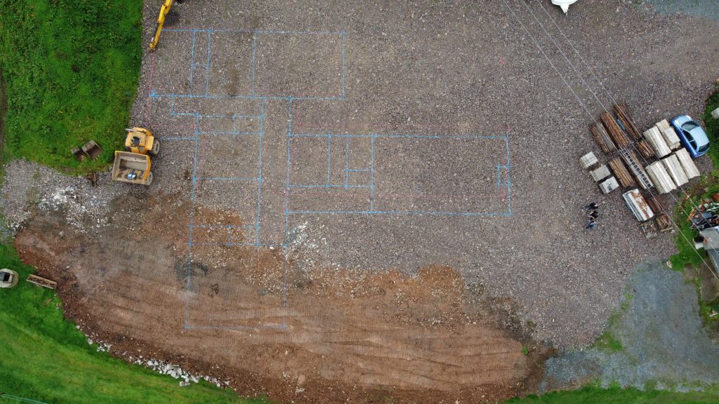
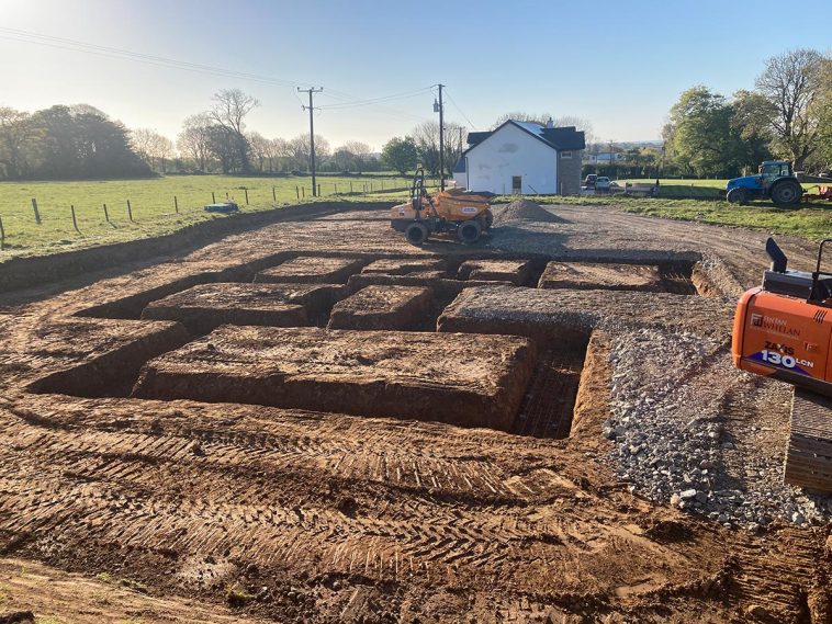
Shape and fill
Foundation excavations must be square (i.e. not rounded) at the bottom and must be excavated down to subsoil which is of consistent load-bearing quality throughout the extent of the foundations under the building. These rules apply equally to strip, raft and mass concrete types of foundations.
Any large boulders or soft pockets of sand, subsoil, fill material or organic material found at the bottoms of foundation trenches must be removed and the space filled up to the underside of the proposed foundation level with lean mix concrete.
In less favourable soil conditions, engineered fill or ground improvement schemes may be necessary. These procedures must be undertaken by a specialist contractor and tested by an engineer.
Water table issues
If the water table could rise to within 250mm of the lowest damp proof membrane (DPM) of the building, or where surface water could enter or adversely affect the building, the ground to be covered by the building should be properly drained.
If the route of an existing active subsoil drain is discovered passing under the building it should be relaid in pipes with sealed joints and have access points before and after it passes under the building, or be rerouted around the building or connected to another outfall.
Adverse soil conditions
Where it is suspected that the site is potentially contaminated (brownfield site), a combined geotechnical and geo-environmental investigation should be considered. On a brownfield site some form of unfavourable ground conditions such as contaminated soil, buried waste or organic fill material might be expected and investigate work should have been carried out of a very easy stage preferably before submitting the planning application.
Adverse soil conditions may be discovered on greenfield sites too. Deep pockets of underlying organic soils are not uncommon and although most may be fine for growing crops, are unfortunately not very good at carrying building loads without some degree of settlement. Because of this and also owing to the fact that some organic soils, such as peat, may produce gases such as carbon dioxide and methane, they may need to be removed if under or near to the building; or the ground ventilated or otherwise treated by a specialised contractor.
The detailed soil analysis in the geotechnical report will allow your structural engineer to design suitable foundations and the geo-environmental report will recommend suitable actions for dealing with contaminated or deep organic soil.
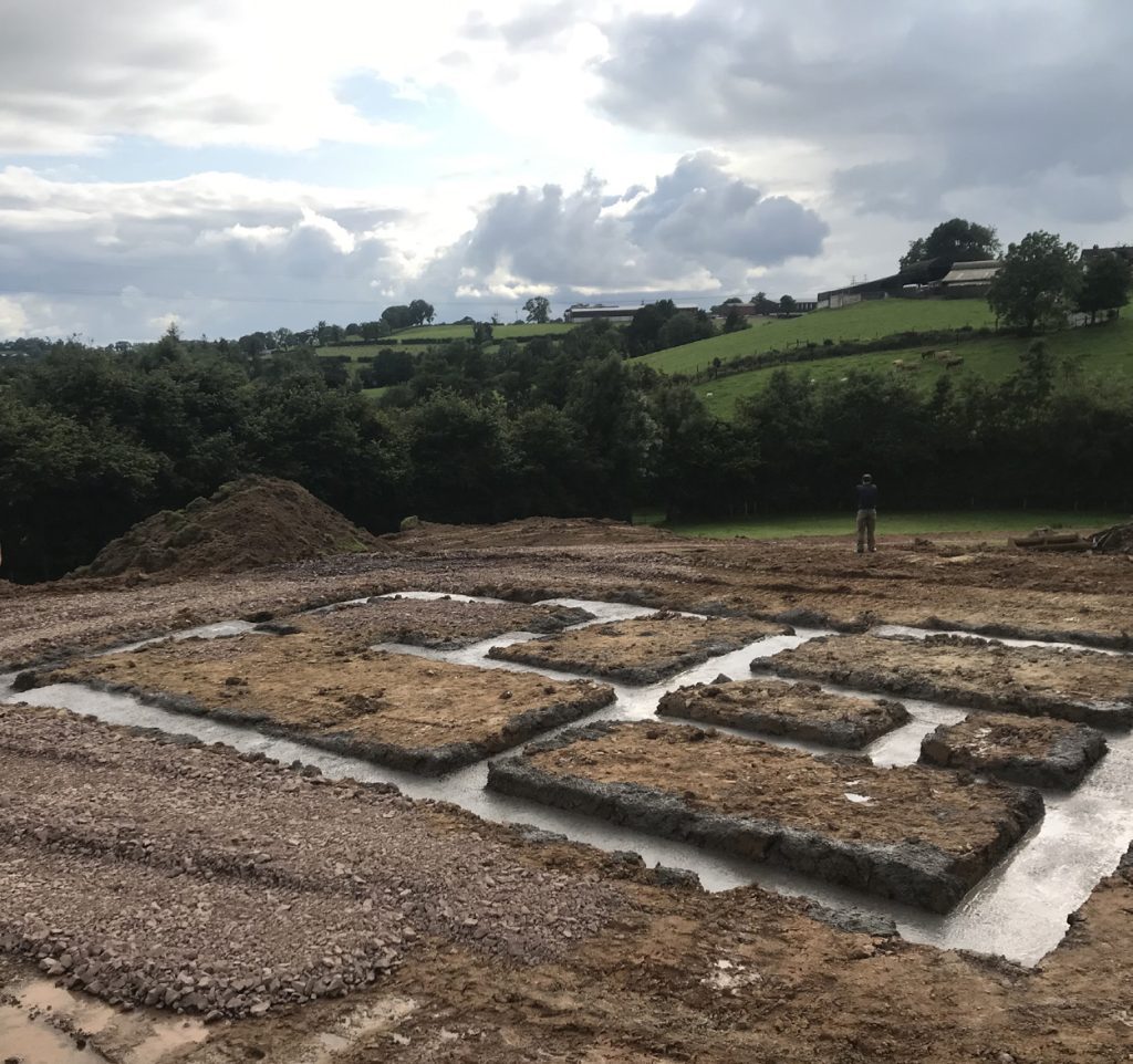
Watchpoints before poring
Before pouring the concrete foundations, the excavations should be tidied up to remove any debris that may have fallen into the trench. All excavations must be kept free from water, and if left open for a long period of time, further excavation down to a non-weathered strata may be required.
Double check that all dimensions are correct for trench lengths, widths, depths and diagonals across the opposite corners of the house. If the soil shows signs of slipping into the trenches, do not excavate more soil to create sloping sides. Even if there was the available horizontal space to do this, a foundation profile could be created which may be unstable.
Instead, provide shuttering to create vertical sides to the trenches. Such trenches may in any case need to be shored and propped in order to comply with health and safety measures.
Regardless of the anticipated depth, a risk assessment should have been carried out by a competent person before carrying out any excavation and should aim to minimise the requirements for operatives to enter an excavation. If this cannot be avoided then shoring and propping would usually be required.
Tragically, fatalities have occurred in trenches as shallow as 1m, so there is no standard minimum depth at which shoring must be provided and its installation is all down to the risk assessment which may vary from site to site.
Fence or tape off exclusion zones on the surface adjacent to trenches for plant, machinery and stored materials. When not being worked at, cover all open holes, including any small diameter ones.
Check the specs
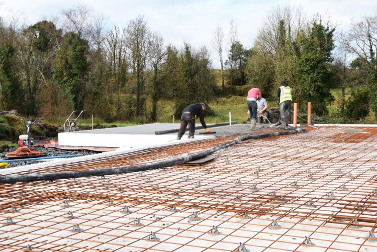
If steel reinforcement has been specified, it must be laid in accordance with the structural engineer’s design and bar schedules and then checked by the structural engineer.
Check that the concrete is supplied in accordance with the specification in terms of strength and slump class.
Water issues
Do not allow the concrete delivery operative to wash out his lorry into the foundations and if washin machinery must be done elsewhere on site, make sure that approved environmental protection measures are in place to take care of it.
After concreting work is complete, prevent water from collecting and always allow sufficient time for the concrete to cure properly before proceeding with building the footings.
If the water in the concrete mix freezes, the concrete will need to be removed, so provide frost protection if the temperature is likely to fall below 5degC.
Footings
Firstly, the term ‘footings’ can mean different things depending on where you come from. For some, the footing is the support for the foundations, for others it is the foundation itself and for yet others it is the part of the base of the wall constructed on top of the foundation and reaching up to about ground level or subfloor level. It is the latter definition which we tend to use in Ireland.
Composition
All footings from foundation level up to a point 225mm below the lowest damp proof course (DPC) will typically consist of dense concrete blockwork without any cavities. Unless designed otherwise, the footings for all walls should be located centrally on the foundations and if any variance in dimensions is found on site, it should be reported right way to the designer or structural engineer.
Footings should be at least as wide as the thickness of the walls above them and it is good practice to construct 215mm wide blockwork footings for 100mm or 140mm thick internal walls. External cavity walls of 400mm in width, would require footings built at 440mm in width to suit the next available blockwork.
Watchpoints for services
After the footings are constructed, fix in position all pipes, ducts, and cables which will pentrate the ground floor and the bases of the walls. This should include radon sumps and their discharge pipes if they have been specified for your site. Check all components for compliance with standards.
Ensure the backfilling avoids displacement for the ducts and drains from their lines and levels. Mechanical compaction equipment should not be used over underground services until there is a minimum of 450mm material above the top of the duct or pipe. Away from these locations, fill should be mechanically compacted in 150mm layers.
Where a drain is liable to surcharge, protective measures such as wrapping int in polythene, bedding and surrounding it in concrete and the provision of movement joints will be required. In some cases, underground services may have to be supported on piles.
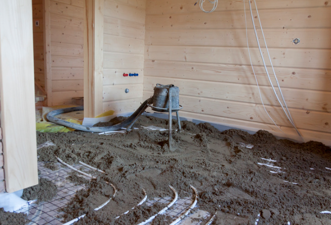
Subfloors and screeds
The subfloor, placed at or near ground level, is a structural element of the building. In cases where the ground floors are suspended, the subfloor is a means of protection for the underfloor void against burrowing pests or vegetation growth, etc.
In a basement, it may form part of a barrier against groundwater and horizontal restraint for the bases of retaining walls.
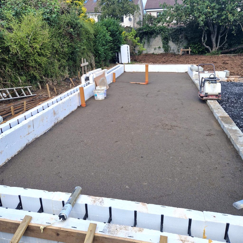
Insulated concrete rafts
Insulated concrete rafts combine the requirements served by foundations and subfloors together, so cost savings on time and materials can be made. The raft may incorporate underfloor heating and it provides a method for maintaining a continuous thermally insulated envelope around and under the building.
These insulated raft structures rely on parts of the insulation to act as load bearing elements, so skill and experience is needed to get it all prepared and installed correctly. If you are tackling one yourself, take advantage of the manufacturer’s on-site supervision and training.
In certain cases, the subfloor may be the only constructed floor element that you need and floor screeds can be avoided altogether, but it is essential to address this at the design stage.
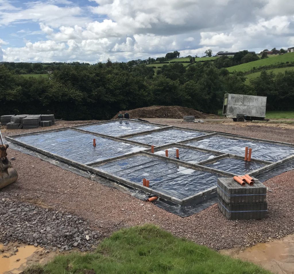
Radon barrier watchpoints
The radon barrier membrane will usually also serve as the damp proof membrane (DPM) and is preferably fitted under the subfloor over a layer of sand blinding on top of the hardcore fill, the top 200mm of which should be gas permeable.
The membrane must extend out past the external face of the external wall, above finished ground level, but it is quite common to find radon barriers which don’t extend out far enough. This is usually due to under-estimating the area of membrane needed to account for rises and dips across the base and the effect of shrinkage which concrete is poured over it.
Radon sumps need to be piped out to the external air and vented above ground level, with the potential for later adding mechanical extract equipment if radon levels are very high. The external ends of the pipes must not permit groundwater or rainwater to pass back into the sump.
The radon barrier / DPM should be at least 300 µm thick (1,200 gauge), CE or UKNI marked as such and with properly sealed joints. All pipes, ducts or similar services which pass through the membrane must be properly sealed using proprietary ‘top hat’ collars.
Needless to say, the membrane and its seals, taped joints and fittings must be gas tight throughout. Failing to repair a puncture is likely to concentrate radon into one point of the dwelling, which is not good, particularly if that point is under a habitable room.
Explainer
What are foundations?
Foundations support building by transferring their loads to the ground. The performance of the foundation depends on the load bearing capacities and settlement characteristics of the layers of rock or soil on which they are placed.
Most of use usually think of them as the continuous strip foundation consisting of concrete cast in trenches directly under the line of each wall to be supported. In fact, the type chosen for your site by your designer will generally be this type of shallow strip foundation, a choice usually based on preliminary assumptions about the soil conditions.
If the ground conditions are found to be unsuitable for strip foundations, then a solution will need to be designed by a structural engineer.
There are two types of foundations, shallow foundations & deep foundations.
Shallow Foundations
Strip types are the most common form of shallow foundations, whereas trench fill foundations are a variation of strip foundations which are usually used where the depth of the trench is deeper than normal, or where it is intended to almost completely fill the trench to take the place of blockwork footings.
A raft foundation consisting of a layer of reinforced concrete over the footprint of the building can be a food solution where ground conditions are inconsistent across the building area or where strip foundations would be impractical, for example where there are individual loads positioned closely together.
Rafts may be locally strengthened where loads are higher.
Pad foundations are used for separate point loads, for instance, under columns supporting parts of the building at higher levels.
Deep Foundations
These are typically formed using a version of piled foundations, upon which are cast reinforced concrete beams to carry the walls above. If a suitable load bearing layer of subsoil cannot be found at relatively shallow depths, the only option is to dig deeper. However, the practical limit of depth for normal foundation trench excavations is, as a general rule of thumb, 2.5 metres.
Below this depth, pile foundations should prove more economical. Driven piles can be steel or precast concrete which are hammered or vibrated down by a piling machine until sufficient resistance is found. These can be end-bearing piles which rely on finding a load bearing stratum at their lower ends, or friction piles which depend on the effects of shear stresses in the soil along their sides when hard layers are too deep.
Pile foundations under houses and extensions are quite often mini – or micro-piles, which can be placed when space is restricted or when loads are not too great. On a site where the vibrations and noise from driven piles would be unacceptable or where the soil is primarily cohesive (e.g. soft clay), screwed or bored piles can be a good option. Screw piles, like their name suggests, are screwed into the soil until sufficient resistance is encountered. Bored piles are created by boring vertical holes into when concrete is poured.
Continuous-flight auger (CFA) piles are formed using a simultaneous boring and pouring process. Other types of deep foundation such as contiguous piled walls, interlocking secant piled walls, sheet piled walls, diaphragm walls or caissons, would usually only be needed for larger buildings.